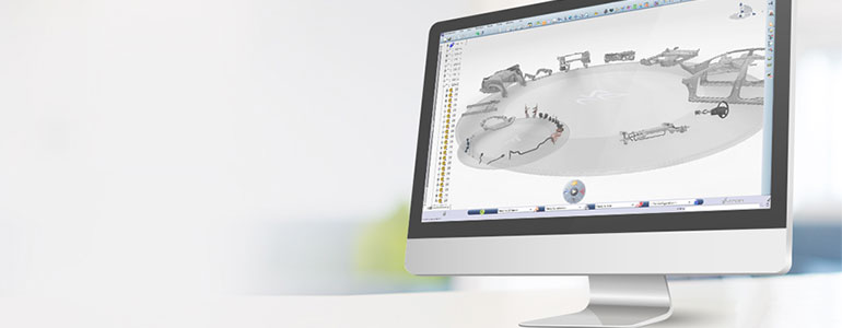
Kinematic Simulations in CATIA… Cool visual animations or a useful engineering tool?
Simulations of assemblies can be manually animated from the Assembly Design workbench by using the Manipulate tool with ‘With Respect To Constraints” switched on. However this is not time based and users can not analyse the kinematic sequence of events.
However using the DMU Kinematic workbench, the user can obtain useful information from during the simulation. For example this could be the position of a reference element based on time throughout the simulation.
Below is an insight to just one aspect of how kinematic simulations in CATIA can assist with the design process of an engineering masterpiece.
This video shows how from the DMU Kinematics workbench, a swept representation of the path of a part(s) can be displayed, or the movement of a reference element. This can all assist with understanding how the kinematics of the assembly behave and/or for clearance/contact/clash detections during the kinematic process of the assembly.

